
Page 160 - DHH Catalog
P. 160
Fluid Port and Connector Thread Sizes HYDRAULIC HOSE
.com ®
NATIONAL PIPE THREADS O-RING CONNECTIONS
There are several variations of pipe threads. Thread forms include the SAE Straight Thread (O-Ring Boss): This fi tting is a modifi cation of the
Dryseal American Standard Taper Pipe Thread (NPTF), the National Pipe male JIC where the beveled 37° nose has been removed and a groove has
Straight Threads for Mechanical Joints (NPSM) and the dryseal American been machined between the threads and the hex in which an O-ring is
Fuel Internal Straight Pipe Thread (NPSF). Each series is normally identifi ed seated. The female is a port which has been tapped to the proper straight
by the abbreviated letter designation. thread size and chamfered at the port face to provide an O-ring seat. The
seal is made when the O-ring is trapped between port chamfer, thread
The NPTF thread is recommended for hydraulic service. This thread series under-cut, and the male fi tting.
is used on both male and female ends and forms a seal by the interference
fi t at the root and crest of the mating threads. The NPTF male also has an O-Ring Face Seal (ORFS): Uses an O-ring (SAE J515) in a groove on the
internal chamfer of 30° which allows it to seal at the seat with female NPSM male face side. This is mated to fl at face with an O-ring on the female
pipe swivels. The NPSM is a straight pipe thread and sealing is obtained by swivel side, forming a seal without metal deformation much the same as
the mating of the 30° seats of the male and female ends. an SAE four bolt split fl ange connection without the bolts. The O-ring face
seal connection has been tested to SAE J343 tests and procedures and
FLARED TUBE FITTINGS meets or exceeds SAE J1453 specifi cations. This connector has proven its
superiority in leak resistance, ease of installation, high operating pressure,
SAE 37° Flare (JIC): The seal is obtained by the mating of two beveled increased torque tolerance and reusability with its ability to be connected
metal surfaces. The function of the threads is simply to draw these two and disconnected frequently.
surfaces together. This style is used particularly in high pressure systems.
As illustrated below, both the bevel on the male and the seat in the female SAE J518 Four-Bolt Flange: Available in two pressure ratings. Code
are machined to 37°. 61 is referred to as the “standard” series and Code 62 is the “6000 psi”
series. The design of both series is the same, but the bolt-hole and fl ange
SAE 45° Flare: These fl ared tube fi ttings are similar to JIC, however the diameters are diff erent. The female port is unthreaded. The male consists
mating surfaces are machined at 45°. These couplings are usually used for of a fl anged head, grooved for an O-ring. The seal is made when the O-ring
low pressure applications such as refrigerant and fuel lines in conjunction is compressed between the fl ange head and the surface surrounding the
with copper tubing which fl ares easily to 45°.
port.
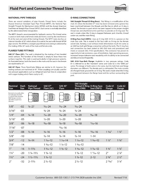
SAE Straight
Nominal Dash National SAE 37° SAE 45° Thread O-Ring O-Ring Face Code 61 Code 62
Size Size Pipe Thread Flare (JIC) Flare Boss (ORB) Seal (ORFS) Flange Flange
Nominal size usually refers
to inside pipe diameter
or outside tube diameter.
With fl anges, nominal
size refers to port hole
diameter.
1/8" -02 1⁄8–27 5⁄16–24 5⁄16–24 5⁄16–24
3/16" -03 3⁄8–24 3⁄8–24 3⁄8–24
1/4" -04 1⁄4–18 7⁄16–20 7⁄16–20 7⁄16–20 9⁄16–18
5/16" -05 1⁄2–20 1⁄2–20 1⁄2–20
3/8" -06 3⁄8–18 9⁄16–18 5⁄8–18 9⁄16–18 11⁄16–16
7/16" -07 11⁄16–16
1/2" -08 1⁄2–14 3⁄4–16 3⁄4–16 3⁄4–16 13⁄16–16 1 3⁄16" 1 1⁄4"
5/8" -10 7⁄8–14 7⁄8–14 7⁄8–14 1–14
3/4" -12 3⁄4–14 1 1⁄16–12 1 1⁄16–14 1 1⁄16–12 1 3⁄16–12 1 1⁄2" 1 5⁄8"
7/8" -14 1 3⁄16–12 1 1⁄4–12 1 3⁄16–12
1" -16 1–111⁄2 1 5⁄16–12 1 3⁄8–12 1 5⁄16–12 1 7⁄16–12 1 3⁄4" 1 7⁄8"
1¼" -20 1 1⁄4–111⁄2 1 5⁄8–12 1 5⁄8–12 1 11⁄16–12 2" 2 1⁄8"
1½" -24 1 1⁄2–111⁄2 1 7⁄8–12 1 7⁄8–12 2–12 2 3⁄8" 2 1⁄2"
2" -32 2–111⁄2 2 1⁄2–12 2 1⁄2–12 2 13⁄16" 3 1⁄8"
Customer Service: 800-535-1302 (1-215-744-2828 outside the USA) Revised 7/18